Arc flash analysis with IEEE 1584 in Electrisim
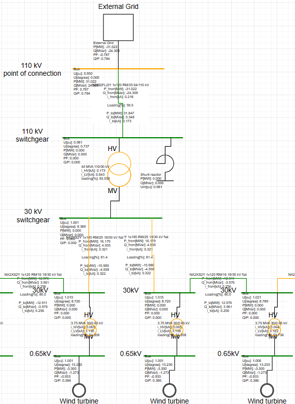
Arc flash estimates thermal hazard at each bus. Electrisim runs a 3-phase maximum short-circuit (IEC 60909), then IEEE 1584-2018 for arcing current, incident energy, arc-flash boundary (AFB), and an NFPA 70E–style PPE category. Results are painted on the diagram.
Where to find it: Simulate → Arc Flash (IEEE 1584). Requires an active subscription. Full dialog reference: Arc flash in documentation.
When to use arc flash studies
- PPE selection from incident energy
- Arc-flash boundary for labelling and approach limits
- Comparing LV feeder hazard (for example MCC vs a remote panel)
How to run
- Build the network and confirm short-circuit data (source impedances, transformer ratings) is filled in.
- Click Simulate → Arc Flash (IEEE 1584).
- Set working distance, electrode configuration, and clearing times, then run.
- Read incident energy, AFB, and PPE category on each applicable bus.
How it is calculated
- Short circuit: 3-phase max fault currents (Ikss) are calculated for all buses.
- Arcing current (Iarc): IEEE 1584-2018 converts bolted fault current to arcing current using electrode configuration, gap, and voltage.
- Reduced arcing current: Iarc-min is evaluated (variation factor); both clearing times are considered and the worst-case energy is kept.
- Incident energy (IE): Energy at the working distance in cal/cm², including enclosure correction factor where applicable.
- Arc-flash boundary (AFB): Distance where IE equals 1.2 cal/cm².
- PPE category: Mapped from IE using NFPA 70E thresholds (Cat 0–4 / Dangerous).
Voltage range and methods
- 208 V – 15 kV: IEEE 1584-2018 empirical model (verified open-source coefficients).
- Above 15 kV: Ralph Lee method; results are tagged so HV estimates are not confused with IEEE 1584 LV/MV results.
- Below 0.208 kV: Bus is skipped as outside the IEEE 1584 applicability range.
Key input parameters
Typical settings in the Arc Flash dialog include electrode configuration (VCB, VCBB, HCB, VOA, HOA), working distance (mm), conductor gap, enclosure dimensions for boxed configurations, and clearing times at nominal and reduced arcing current. VCB (vertical conductors in a metal box) is a common default for switchgear and MCC.
Electrode configurations (IEEE 1584)
- VCB — Vertical conductors in a metal box (typical switchgear / MCC)
- VCBB — Vertical conductors terminated in an insulating barrier inside a box
- HCB — Horizontal conductors in a metal box (often higher IE)
- VOA — Vertical conductors in open air
- HOA — Horizontal conductors in open air
Feeder length and clearing time alone can swing PPE from Category 0 to Category 2 — same voltage, same transformer, very different risk. Run arc flash after your short-circuit study is consistent: app.electrisim.com.
Related: Short circuit analysis guide, 33 MW wind farm short-circuit walkthrough, and ETAP alternative for load flow, short circuit, and arc flash in one browser tool.