- Home
- Documentation
- Short circuit
Short Circuit
pandapower OpenDSS ANSI/IEEE C37
Short Circuit calculates fault currents on the network so you can size breakers, check withstand, and feed protection studies. Two engine tabs are available and are not interchangeable: Pandapower can run IEC 60909 or ANSI/IEEE C37 (beta) (tick boxes on that tab); OpenDSS runs a native Thévenin fault study.
Simulate → Short Circuit. Pick Pandapower (then tick IEC 60909 or ANSI/IEEE C37) or OpenDSS before you run.
When to use
- Breaker and fuse ratings: peak (making), breaking current and DC component at contact parting, with a pass/fail check of each circuit breaker
- Relay pickup and protection coordination
- Grid-code style IEC 60909 studies (Pandapower tab, IEC 60909 tick)
- North American / Canadian projects requiring ANSI/IEEE C37 duties (Pandapower tab, ANSI/IEEE C37 tick — currently beta; default 60 Hz, prefault 1.0 pu)
How to run
- Confirm the diagram already solves in Load Flow with the same engine you will use for faults.
- Click Simulate → Short Circuit and choose the engine tab. On Pandapower, tick IEC 60909 or ANSI/IEEE C37 (beta).
- Set fault type (3-phase, 2-phase, or 1-phase), case (maximum or minimum), and Fault location (All busbars, or User Selection of one or more busbars). For IEC 60909 single-phase minimum, fill the External Grid Short Circuit tab, including min zero-sequence ratios.
- Read currents on the diagram. A red thunder mark sits on each faulted busbar (all buses, or the User Selection). It is removed when you run the next study of any type. Pandapower writes buses, lines, transformers, and the external grid. OpenDSS writes bus currents only; line, transformer, external-grid, and wind-turbine result boxes are marked as not provided. The Short-Circuit Dashboard opens automatically after a successful run.
- Optional: tick Export Pandapower Python Code (IEC Pandapower), Export OpenDSS Commands (OpenDSS tab), or Export PDF Engineering Report before you run.
- Use those values for Arc Flash if you need incident energy next.
IEC 60909 (Pandapower) uses the IEC voltage factor and correction factors. ANSI/IEEE C37 (beta) uses prefault voltage (no IEC c-factor) and C37.010/C37.13/UL 489/C37.013 multiplying factors. OpenDSS is a generic Thévenin fault study. Compare numbers only within the same method, and size breakers to the same standard as the calculation.
How the calculation is set up
The study uses sequence impedances, applies a fault impedance at the chosen location, builds a Thévenin equivalent, computes the fault current for the selected fault type, and distributes branch contributions through the network.
- Pandapower — IEC 60909 — IEC 60909 via pandapower short-circuit calculation, plus the breaking current, DC component and asymmetrical breaking current at contact parting, and an IEC 62271-100 check of each circuit breaker (see Breaking current and breaker check). Use for balanced three-phase networks and grid-code style studies.
- Pandapower — ANSI/IEEE C37 (beta) — Three networks (1/2-cycle, interrupting, 30-cycle) with IEEE C37.010-style multiplying factors. Does not call pandapower IEC
calc_sc. Outputs I1/2 sym, I1/2 peak, Iint, I30, X/R per bus, plus line and transformer currents (also written onto diagram result boxes), and breaker duty checks when Switch ratings are entered. Verify against utility requirements before using results for equipment ratings. - OpenDSS tab — native OpenDSS FaultStudy. Reports symmetrical, peak, and thermal currents per bus only. Assumptions differ from IEC 60909; see Pandapower vs OpenDSS.
ANSI/IEEE C37 (North America / Canada) — beta
ANSI/IEEE C37 short circuit is in beta. Use results for engineering review. Verify against utility or consultant practice before applying them to equipment ratings.
On the Pandapower tab, tick ANSI/IEEE C37 when the project or utility requires ANSI/IEEE C37 short-circuit duties (typical in Canada and the United States). This is not IEC 60909 with a different label.
The study follows the North American three-network method used in IEEE C37.010 (and described in IEEE Std 141, the Red Book). Electrisim builds three separate impedance networks from the same diagram:
- First-cycle (½-cycle) — subtransient machine reactances. Momentary / close-and-latch basis.
- Interrupting — contact parting time (default 3 cycles). Transient reactances; motors reduced or removed per ANSI practice.
- 30-cycle — steady-state network (induction motors out).
Prefault voltage is applied directly (default 1.00 pu). There is no IEC voltage factor c and no IEC KG / KT correction factors. Asymmetry uses the calculated fault-point X/R: first-cycle peak from a fully offset wave, interrupting duty from the remaining DC component at contact parting (compared with the C37.010 X/R = 17 test circuit for symmetrically rated HV breakers), and extra first-cycle derating for LV devices when system X/R exceeds the C37.13 (6.6) or UL 489 (4.9) test circuit.
Set generator ANSI machine type (turbo, hydro, etc.) and Switch interrupting / momentary ratings on the Short Circuit tab for duty comparison. Device class can be auto (from voltage) or C37.010 / C37.13 / UL 489 / C37.013.
The momentary duty is a peak current, so it is compared with a peak rating. When the momentary (close-and-latch) rating is left at 0, Electrisim uses the peak the device standard ties to the interrupting rating: 2.6 × for HV breakers (IEEE C37.04, 2.5 × at 50 Hz), 2.74 × for generator breakers (IEEE C37.013), and the first-cycle peak of the test circuit for LV breakers (X/R 6.6 for C37.13, 4.9 for UL 489). The results mark such a rating as derived. The switch's rated current (In) is never used as a short-circuit rating.
IEC 60909 vs ANSI/IEEE C37
| IEC 60909 | ANSI/IEEE C37 (beta) | |
|---|---|---|
| Voltage | Voltage factor c (e.g. 1.1) | Prefault pu (typically 1.0) |
| Machines | IEC correction factors | Separate ½-cycle / interrupting / 30-cycle networks |
| Peak / interrupting | κ, ip, Ib, iDC at tmin | X/R multiplying factors (C37.010 / C37.13 / UL 489) |
| Breaker check | IEC 62271-100: making current, Isc, DC component | Interrupting and momentary ratings |
| Typical use | Europe, IEC-rated gear | Canada / US, ANSI-rated gear |
ANSI results
Currents are written to diagram result boxes on buses, lines, and transformers, and listed in the ANSI results dialog (and optional TXT export).
| Result | Meaning |
|---|---|
| I1/2 sym | First-cycle symmetrical RMS (subtransient network) |
| I1/2 peak | First-cycle peak (momentary / close-and-latch duty basis) |
| Iint | Interrupting duty at contact parting time (C37.010) |
| I30 | 30-cycle steady-state symmetrical current |
| X/R | Fault-point X/R for multiplying-factor application |
| Line I from / I to | Worst-case branch end currents over the chosen fault locations (all busbars, or User Selection). 3-phase and line-to-line only. |
| Transformer I HV / I LV | Worst-case HV and LV side currents |
| Device duty | Pass/fail against Switch interrupting and momentary ratings, when entered. A momentary rating left at 0 is derived from the interrupting rating and marked derived. |
ANSI input parameters
| Parameter | Description | Default |
|---|---|---|
| Fault | 3-phase, 2-phase, or 1-phase. Line and transformer branch currents are reported for 3-phase and 2-phase faults (positive-sequence network). Single-phase branch flows are omitted because the zero-sequence branch model is approximate. | Three Phase |
| Fault location | All busbars (default), or User Selection of one or more busbars. Tick busbars in the dialog, or select them on the diagram first. Branch currents then use only those fault locations. | All busbars |
| System frequency | Used for DC decay and contact-parting time | 60 Hz |
| Prefault voltage | Driving voltage in pu (no IEC c-factor) | 1.00 pu |
| Contact parting time | Breaker contact parting in cycles (interrupting network) | 3 cycles |
| Fault R / X | Optional fault impedance in ohm | 0 |
ANSI limitations (beta): do not mix ANSI currents with IEC-rated equipment. Single-phase line/transformer currents are not published. Arc flash still uses the IEC 60909 path. Spot-check a few duties against your C37.010 tables or a known hand calc before relying on ratings.
Fault types
Electrisim supports three types of short circuit faults:
- Three-Phase Fault (3ph): Symmetrical fault affecting all three phases. Typically produces the highest fault current. Used for symmetrical interrupting capacity rating.
- Two-Phase Fault (2ph): Fault between two phases. Produces lower fault current than three-phase. Used for phase-to-phase protection.
- Single-Phase Fault (1ph): Fault between one phase and neutral/ground. Includes zero-sequence impedance of the network and of the External Grid. Critical for ground-fault protection and neutral sizing. IEC 60909 maximum uses
r0x0_max/x0x_max; minimum usesr0x0_min/x0x_min.
Fault location is independent of fault type. All busbars (default) applies the chosen fault at every bus. User Selection applies it only at the busbars you tick in the dialog (busbars selected on the diagram are pre-ticked). Unselected bus result boxes show “Fault not applied”. A red thunder sign marks each faulted bus on the diagram until the next simulation.
Input Parameters (IEC 60909)
These fields appear when IEC 60909 is ticked on the Pandapower tab. For ANSI parameters see ANSI/IEEE C37 above.
| Parameter | Description | Type | Options/Value Range | Default |
|---|---|---|---|---|
| Fault | Type of short circuit fault | radio | Three Phase (3ph), Two Phase (2ph), Single Phase (1ph) | Three Phase |
| Fault location | Where the fault is applied. All busbars computes Ikss at every bus. User Selection limits the study to the ticked busbars (pre-ticked from the diagram selection). Unselected bus result boxes show “Fault not applied”. | radio | All busbars, User Selection | All busbars |
| Case | Fault current calculation case. IEC 60909 maximum uses External Grid max short-circuit data; minimum uses min data. Single-phase minimum also needs r0x0_min and x0x_min (see External Grid). |
radio | Maximum (max), Minimum (min) | Maximum |
| Voltage Tolerance in LV Grids | Voltage tolerance factor for low voltage networks | radio | 6%, 10% | 6% |
| Topology | Network topology classification | radio | Auto, Radial, Meshed | Auto |
| Failure Clearing Time (s) | Fault duration for thermal rating (ith calculation) | number | > 0 | 1.0 |
| Contact parting time tmin (ms) | Relay time plus the minimum opening time of the breaker: the instant the contacts separate. The breaking current Ib, the DC component iDC and the breaker check are taken here. A breaker with its own contact parting time uses that one. | number | > 0 | 50 |
| Fault Resistance (Ohm) | Resistance at fault location (for arc fault modeling) | number | ≥ 0 | 0 |
| Fault Reactance (Ohm) | Reactance at fault location | number | ≥ 0 | 0 |
| Inverse Should Be Used Instead of LU Factorization | Solution method preference | radio | True, False | True |
| Export Pandapower Python Code | Download generated Python that rebuilds the network and runs pandapower.shortcircuit.calc_sc (IEC 60909 only) |
checkbox | Yes/No | No |
| Export Pandapower Results | Download bus and branch short-circuit results as a .txt file | checkbox | Yes/No | No |
| Export PDF Engineering Report | Multi-page short-circuit PDF (see Short-Circuit Engineering Report) | checkbox | Yes/No | No |
Short-Circuit Dashboard
After a successful short-circuit run (Pandapower IEC, ANSI/IEEE C37, or OpenDSS), Electrisim opens the Short-Circuit Dashboard: the same floating panel pattern as the load-flow Network Health Dashboard, but KPIs use fault currents (Ikss, Ip, Ith, X/R) instead of voltage and loading.
What you see: study score (0–100), max/min Ikss, peak and thermal currents, top fault-level buses and branches (click to focus on the SLD), Ikss histogram, critical issues (missing data, high fault levels, ANSI device duty fails, IEC breakers that fail or need confirming), the Circuit Breakers (IEC 62271-100) table after an IEC 60909 run (see breaker check), Highlight Hot Spots, Fault current waveform (see below), Copy Summary, and Export Report for the short-circuit PDF.
Scenario Compare and Line current vs km remain load-flow-only tools.
Fault Current Waveform
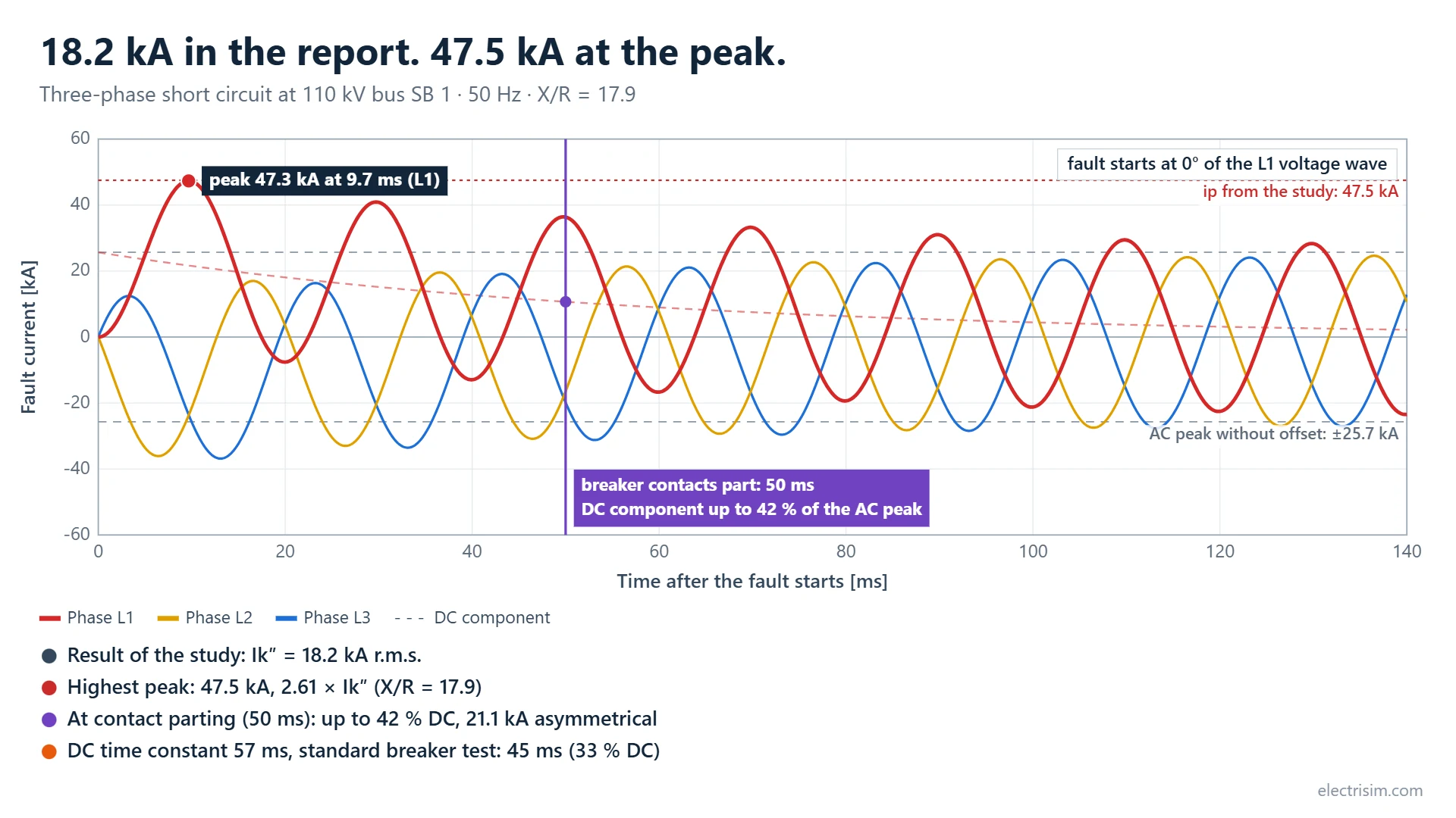
A short-circuit study gives r.m.s. values. The Fault Current Waveform window shows what those values look like in time: the three phase currents with their DC offset, the first peak, and the current the breaker meets when its contacts part.
Run a short circuit, then click Fault current waveform… on the Short-Circuit Dashboard. It opens on the bus with the highest fault level. Works with IEC 60909 and ANSI/IEEE C37 results.
| Control | What it does | Default |
|---|---|---|
| Fault at | The faulted bus. Buses are listed from the highest to the lowest fault current. | Bus with the highest Ik″ |
| Frequency | 50 or 60 Hz. Sets the time axis and the DC time constant. | 50 Hz (IEC), study frequency (ANSI) |
| Contacts part after [ms] | Time from the start of the fault until the breaker contacts separate: relay time plus the minimum opening time of the breaker. | tmin of the IEC study (50 ms) |
| Fault starts at | Angle of the L1 voltage wave at the instant the fault starts. It decides how much DC offset each phase gets. Worst case sets the angle with the highest peak; No offset sets the angle at which L1 has no DC component. | Worst case |
What you read from it
- Peak at this angle, next to ip from the study.
- DC time constant and X/R.
- DC at contact parting in percent of the AC peak, next to the value a standard breaker is type-tested with (DC time constant 45 ms, IEC 62271-100).
- Breaking current Ib (IEC 60909 results): the AC component when the contacts part, with the decay of generators and motors.
- Asymmetrical breaking current: the r.m.s. value of the AC and DC components together at contact parting.
For IEC 60909 results these values come from the study itself when the contacts part at the study's tmin: the same Ib, iDC and Ib,asym as in the breaker check. At other times, and for ANSI results, they come from the curve.
When the DC time constant of the network is above 45 ms, the window says so: check the breaker against its rated DC component, or use a breaker with a special-case time constant.
Play draws the curve and then turns the instant of the fault through one full cycle. Save image (1080×1350 or 1920×1080), Export video and Download CSV export the chart and its data.
How the curve is built, and its limits
The curve is built from the study result. It is not an electromagnetic transient simulation.
- Each phase current is an AC component of √2·Ik″ plus a DC component that makes the current start at zero and decays with the time constant τ = X / (ωR).
- The curve's X/R comes from the IEC 60909 peak factor of the study, κ = ip / (√2·Ik″), so its first peak matches ip. For ANSI results it is the X/R of the study. If neither is available, Xk/Rk at the fault point is used.
- κ uses the R/X of method C at 20 Hz (50 Hz systems). IEC 60909-0 takes the DC component at time t from method C at a lower equivalent frequency that depends on f·t, so in a meshed network the study's iDC and the curve's single time constant differ. In a radial network both give the X/R of the fault point. The tiles use the study's iDC at its tmin.
- The curve keeps the AC component constant (fault far from generators). Close to generators and motors the AC component decays: the study's Ib includes that decay, the curve does not.
- For single-phase and two-phase faults one fault current is drawn.
Short-Circuit Engineering Report (PDF)
Tick Export PDF Engineering Report in the Short Circuit dialog (any engine tab), or click Export Report on the Short-Circuit Dashboard after a run. The PDF includes cover metadata, executive summary with fault-current KPIs, single-line diagram pages, bus and branch tables, the breaking currents at contact parting and the IEC 62271-100 circuit-breaker check (IEC 60909), ANSI device duties when applicable, and an issues list.
Calculation Cases (IEC 60909)
According to DIN/IEC EN 60909, different calculation cases are used:
- Maximum Case (Ik"): Highest fault current (typically for breaker sizing). Assumes maximum generation, minimum impedances, voltage = 1.1 pu (cmax). External Grid uses
s_sc_max_mva,rx_max, and for 1-phase faultsr0x0_max/x0x_max. - Minimum Case (Ik'): Lowest fault current (typically for protection coordination). Assumes minimum generation, maximum impedances, voltage = 0.9 pu (cmin). External Grid uses
s_sc_min_mva,rx_min, and for 1-phase faultsr0x0_min/x0x_min.
Single-phase minimum (IEC 60909): pandapower builds the external-grid zero-sequence impedance from r0x0_min and x0x_min. Set them on the External Grid dialog Short Circuit tab (Min R0/X0 Ratio, Min X0/X Ratio). If they were never stored on an older diagram, Electrisim copies the matching maximum ratios so the study can still run. Typical values when the utility does not give separate min data: R0/X0 ≈ 0.1, X0/X ≈ 1.0. Also set s_sc_min_mva > 0. See External Grid.
Output Results (IEC 60909)
The IEC 60909 analysis reports, for every bus with a fault applied:
| Output Category | Parameters | Description | Units |
|---|---|---|---|
| Initial Symmetrical Current | Ik″ (ikss) | Fault current at t = 0, symmetrical r.m.s. | kA |
| Peak Current | ip | Highest instantaneous fault current, including the DC offset (κ by method C). Single-phase faults use the bus's three-phase κ. | kA |
| Thermal Current | Ith | Equivalent r.m.s. current for the failure clearing time | kA |
| Short-Circuit Impedance | Rk, Xk | Impedance at the fault point | Ω |
| Breaking Current | Ib | Symmetrical breaking current when the contacts part (tmin), with the decay of generators and motors | kA |
| DC Component | iDC, DC % | DC component at tmin, and in percent of the AC peak √2·Ib | kA, % |
| Asymmetrical Breaking Current | Ib,asym | √(Ib² + iDC²) at tmin | kA |
| DC Decay | X/R (DC), τ | The X/R behind iDC (method C) and its time constant τ = X/(ωR) | -, ms |
| Branch Contributions | Line and transformer Ik″, ip, Ith | Worst current at each branch end over the fault locations, with the fault bus that causes it | kA |
| External Grid | Ik″, ip, Ith, Ib, iDC | The values of the bus the grid is connected to | kA |
| Circuit Breakers | Making, breaking, DC | IEC 62271-100 check of each circuit breaker (see below) | - |
Bus result boxes on the diagram show Ik″, ip, Ith, Rk and Xk. The breaking values are on the dashboard, in the results TXT export and in the PDF report.
Breaking current and breaker check (IEC 60909 / IEC 62271-100)
The r.m.s. fault current does not size a breaker on its own. A circuit breaker must make (close onto) the first peak ip, and break the current that flows when its contacts part: an AC component Ib plus a DC component iDC. The IEC 60909 study reports both at every bus, at the contact parting time tmin of the Short Circuit dialog, and checks each circuit breaker against its ratings.
How Ib and iDC are calculated
- DC component (IEC 60909-0, 4.4): iDC = √2·Ik″·e−2πft·R/X. R/X comes from method C: the network is solved at an equivalent frequency fc, with fc/f = 0.27, 0.15, 0.092 or 0.055 for f·t below 1, 2.5, 5 or 12.5 (0.092 at 50 Hz and 50 ms). This is not the 20 Hz R/X behind κ. In a radial network it equals the X/R at the fault point. In a meshed network it is usually higher than the 50 Hz fault-point value, because the paths with a low X/R lose their DC component first. Converters (full-converter wind turbines, PV) carry no DC component. For single-phase faults the three-phase R/X is applied to the whole Ik1″, as for ip.
- Breaking current (IEC 60909-0, 4.5): three-phase faults use the formula for meshed networks, which also covers a single-fed fault. Each synchronous generator lowers Ib by (ΔU″G / (cUn/√3))·(1 − μ)·I″kG, each asynchronous machine (motor or induction generator) by (ΔU″M / (cUn/√3))·(1 − μq)·I″kM. The partial currents and terminal voltages come from the same impedance matrix as Ik″. μ depends on I″kG/IrG and tmin (μ = 1 up to a ratio of 2); q on the rated power per pole pair, taken with one pole pair (the largest q). IEC 60909-0 gives μ and q for 20, 50, 100 and ≥ 250 ms; other times are interpolated linearly. External grids, converters and doubly fed generators keep their initial current. For two-phase and single-phase faults IEC 60909-0 takes Ib = Ik″.
Circuit-breaker check (IEC 62271-100)
Each switch of type CB, and any switch with a rated breaking current, is checked against the fault at its bus: the full bus current, which is the conservative duty. For a bus coupler the larger of its two buses is used. Set the ratings on the Switch dialog, Short Circuit tab:
| Rating | Meaning | When left at 0 |
|---|---|---|
| Rated short-circuit breaking current Isc | Symmetrical r.m.s. (IEC 62271-100) | No breaking or making check |
| Rated making current (peak) | Peak current the breaker can close onto | 2.5 × Isc at 50 Hz, 2.6 × at 60 Hz; 2.7 × for a DC time constant above 45 ms |
| Rated DC time constant | 45 ms standard; 60, 75 or 120 ms special cases | 45 ms |
| Rated DC component | % at contact parting, from the manufacturer | 100·e−t/τ (33 % at 50 ms with 45 ms) |
| Contact parting time | This breaker's relay time plus minimum opening time | The study's tmin |
| Check | Pass when |
|---|---|
| Making | ip ≤ rated making current |
| Breaking | Ib ≤ Isc |
| DC | DC % ≤ rated DC %. When it is above, but Ib,asym ≤ Isc,asym = Isc·√(1 + 2p²) (p = rated DC % / 100), the result is CHECK: the total current is within what the breaker is rated for, the DC share is not. Confirm with the manufacturer, or choose a breaker with a longer rated time constant. Above both: FAIL. |
| Result | FAIL if any check fails, CHECK if the DC component needs confirming, PASS otherwise, NOT RATED without ratings |
Example. Ik″ = 18.2 kA, ip = 47.5 kA (2.61 × Ik″) and X/R = 17.9 (τ = 57 ms) at 50 Hz, no machines nearby, contacts parting at 50 ms. Then Ib = 18.2 kA, iDC = 10.7 kA (42 % DC) and Ib,asym = 21.1 kA. A 20 kA breaker with the standard 45 ms time constant: making 2.5 × 20 = 50 kA ≥ 47.5 kA, PASS; breaking 18.2 kA ≤ 20 kA, PASS; DC 42 % against 33 % rated, with Ib,asym 21.1 kA ≤ Isc,asym 22.1 kA: CHECK. The peak is above 2.5 × Ik″, so the making current is the tighter check, which comparing Ik″ with Isc alone would not show.
The results appear on the Short-Circuit Dashboard (Circuit Breakers table, duty checks KPI, critical issues), in the results TXT export and in the PDF report. The exported Python script carries the same calculation and prints the same numbers.
Algorithm Details (IEC 60909)
The IEC path follows DIN/IEC EN 60909:
- Voltage Factor (c): cmax = 1.1 for maximum case, cmin = 0.9 for minimum case (low voltage)
- Impedance Correction: Generator and transformer impedances are corrected according to the standard
- Peak current: κ by method C (equivalent frequency 20 Hz at 50 Hz, 24 Hz at 60 Hz); converters add their current without a DC offset
- Breaking current and DC component: Ib by the IEC 60909-0 formula for meshed networks, with μ and q, for three-phase faults (Ib = Ik″ for unbalanced faults); iDC with R/X from method C at the equivalent frequency for f·t. See Breaking current and breaker check.
- Solution Method: Matrix inversion or LU factorization of network admittance matrix
Limitations and Considerations
Important Notes:
- Calculations assume balanced pre-fault conditions and symmetrical source impedances
- Fault resistance/reactance can be specified but arc fault modeling may require additional considerations
- Results are based on steady-state fault analysis - dynamic transients are approximated
- Motor contributions to fault current may require special modeling. For Ib, each asynchronous machine is taken with one pole pair (the largest q); a machine with more pole pairs decays faster.
- Grounding system impedance significantly affects single-phase fault currents. For IEC 60909 1-phase faults, the External Grid zero-sequence ratios (
r0x0_max/x0x_maxorr0x0_min/x0x_min) must be set for the selected case. - Results are valid for the specified fault location - multiple fault locations require separate calculations
- Relay and breaker operating characteristics are not modeled: the contact parting time tmin is an input of the study and of each breaker
Short Circuit based on OpenDSS
In addition to Pandapower IEC 60909 and ANSI/IEEE C37 (beta), Electrisim offers short circuit calculation based on OpenDSS. In the Short Circuit dialog, select the OpenDSS tab to run a conventional fault study using the Open-Source Distribution System Simulator.
OpenDSS fault study (Solve Mode=FaultStudy) computes for every bus:
- Initial symmetrical short-circuit current (I''k, ikss) in kA
- Peak short-circuit current (ip, ip) in kA — Electrisim reports
ip = 1.8 · √2 · ikss(fixed κ = 1.8), not the IEC κ(R/X) peak - Thermal short-circuit current (Ith, ith) in kA — copied from ikss (OpenDSS does not compute the IEC 1 s thermal equivalent)
- Positive-sequence short-circuit resistance (Rk, rk_ohm) and reactance (Xk, xk_ohm) in ohms from
Zsc1
Fault type (e.g. 3-phase), Fault location (All busbars or User Selection), and frequency can be set in the OpenDSS tab. Results are shown on the diagram at each faulted busbar. Line, transformer, external-grid, and wind-turbine result boxes are updated to state that OpenDSS does not provide short-circuit currents for those elements (FaultStudy is bus Isc/Zsc only). Optional checkboxes: Export OpenDSS Commands (replay script .txt), Export OpenDSS Results (tabular .txt), and Export PDF Engineering Report (see Short-Circuit Engineering Report). This option uses the same network model as OpenDSS load flow (buses, lines, loads, generators, external grid).
Pandapower vs OpenDSS short-circuit results
The two engines can be run on the same diagram and will usually not return the same kA. That is expected: they implement different methods, not two numerical solvers of IEC 60909.
| Pandapower (IEC 60909) | OpenDSS FaultStudy | |
|---|---|---|
| Standard / method | IEC 60909 equivalent voltage source at the fault | Y-matrix study: Isc = Ysc · Voc from a snapshot |
| Driving voltage | Voltage factor c (typically cmax = 1.10 on MV) | Pre-fault bus voltage from the snapshot (~1.0 pu) |
| Transformers | Nameplate vk with IEC KT correction | Nameplate XHL (vk) without IEC KT |
| Wind turbines / static generators | IEC current sources. Wind turbines use the fault-specific Ik" on the Short Circuit tab when it is > 0 (k = Ik · √3 · Uref / Sn); otherwise k if it is > 0; otherwise k = 1.1. Static generators use k the same way. A minimum study omits the converter current. See Wind Turbine. | OpenDSS Generator behind Xdpp (default 0.2 pu), i.e. a synchronous-machine subtransient model — much larger infeed than IEC type-4. Machine result boxes are not filled with a separate Ikss |
| Shunt capacitors | Typically neglected for maximum Ikss | Included in the nodal Y matrix |
| Peak current ip | IEC κ from R/X (method C) | Fixed κ = 1.8 in Electrisim |
| Thermal Ith | IEC equivalent for the clearing time tk | Set equal to ikss |
| Where results appear | Buses, lines, transformers, external grid | Buses only. Line, transformer, external-grid, and wind-turbine boxes state that OpenDSS does not provide those currents |
Typical pattern on a wind-farm feeder: OpenDSS Ikss is a few percent higher on MV/LV turbine buses (machine Xdpp infeed) and about 1/cmax lower on a capacitor LV bus with no turbine (no IEC voltage factor). Peak currents differ more because of the κ formula.
For breaker ratings, grid-code IEC studies, and comparison with utility IEC figures, use Pandapower IEC 60909. For ANSI-rated gear, use ANSI/IEEE C37. Treat OpenDSS FaultStudy as an IEEE-style Y-bus check, not as IEC Ikss.
OpenDSS references: Fault Studies, Fault Study Mode, Bus.Isc().
Technical References
Based on: pandapower Short-Circuit and DIN/IEC EN 60909 (Pandapower IEC); IEEE C37.010 / C37.13 / UL 489 / C37.013 and IEEE Std 141 three-network method (Pandapower ANSI/IEEE C37, beta); OpenDSS Fault Studies (OpenDSS).
Algorithm Type: Pandapower IEC: symmetrical components with impedance-based fault calculation following IEC 60909. Pandapower ANSI: three impedance networks plus X/R multiplying factors (does not call IEC calc_sc). OpenDSS: conventional fault study with Thévenin equivalent and open-circuit voltage per bus.
Documentation References: 📘 pandapower Short-Circuit 📘 Running a Short-Circuit Calculation 📗 OpenDSS Fault Studies
Standards: IEC 60909: Short-circuit currents in three-phase a.c. systems (Pandapower IEC); IEEE C37.010, IEEE C37.13, UL 489, IEEE C37.013, IEEE Std 141 (Pandapower ANSI, beta).
Last updated: November 2026